Our Projects
Jedan od interesantnijih projekata koje smo imali, možete pronaći u nastavku.
Tipper machine
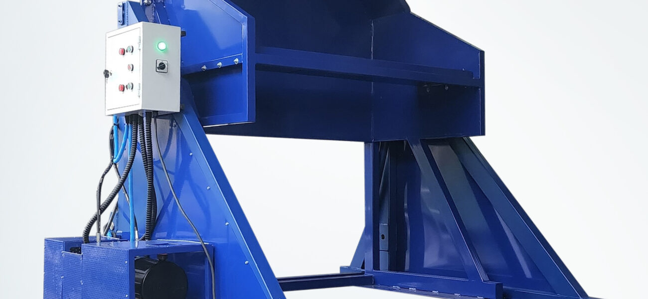
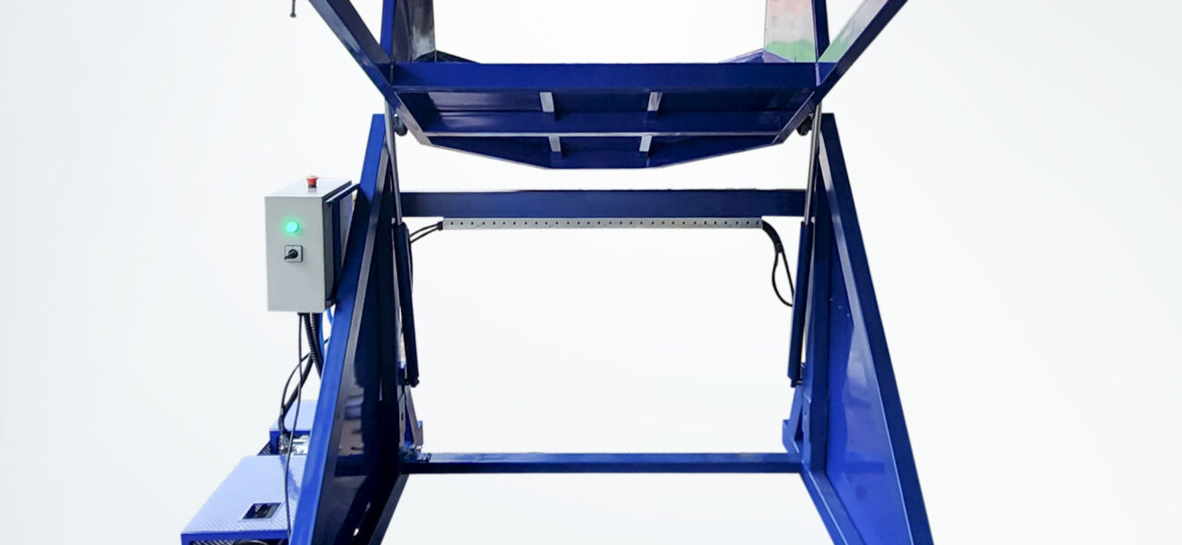
Tipper machine for pouring parts from the gitterbox.
Due to the heavy weight and quantity of parts in the gitterbox that need to be transferred to another gitterbox in order for the parts to go to the next processing stage, a Tipper machine was created that has the task of transferring parts from one box to another.
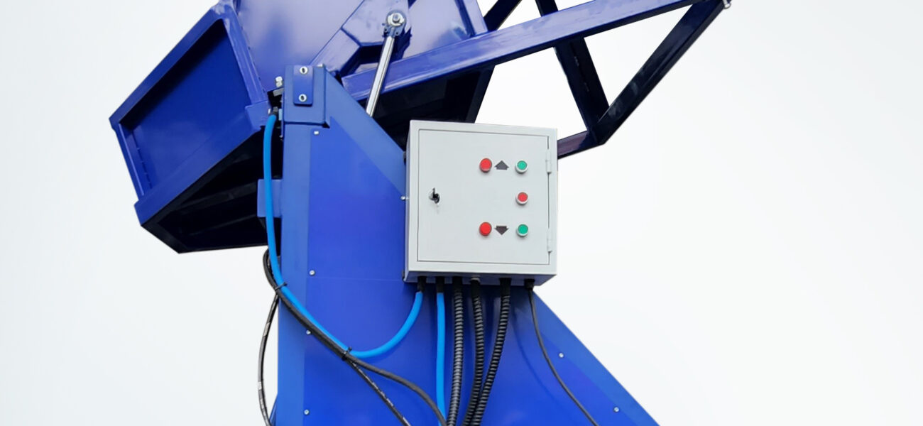
Only one operator is enough for the whole process. The operator will, first of all, place the gitterbox with a forklift or a pallet truck in a position inside the tipper machine that is in the initial, vertical position, and with the command, he will lift the box, which will be in the position from which the parts will be poured. The end position is set to stop 2 cm above the second gitterbox. Gravity will transfer the parts from one box to another box.
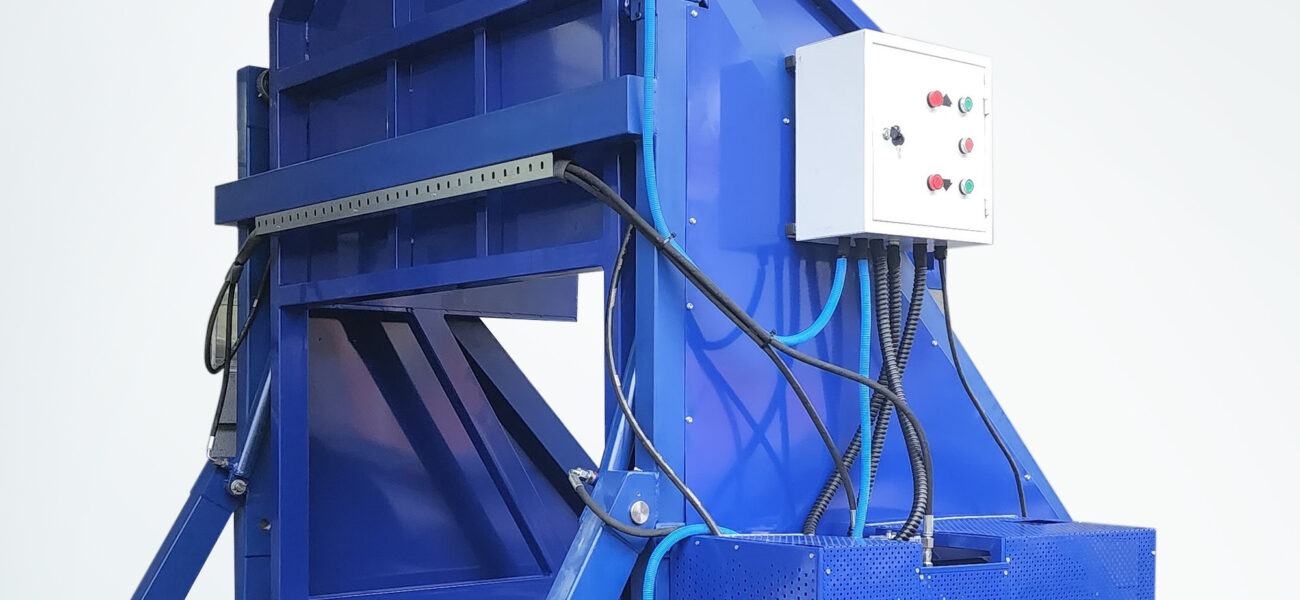
The device is managed from the control cabinet. There are three buttons for starting and stopping (start/stop). Two are for starting one or the other direction, while one is for stopping.
The drive is hydraulic.
The basis of the construction is a robust chassis, which is used to hold the gitterbox and accommodate the power unit. In the part where the gitterbox is located, steel profiles are placed as stops so that the gitterbox remains in the same position even after the end position of the tipper machine.
Due to the presence of dynamic forces during rotation, the machine is fixed to the base.
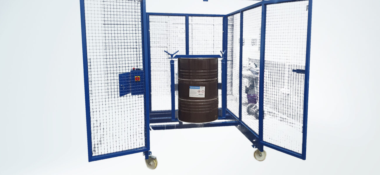
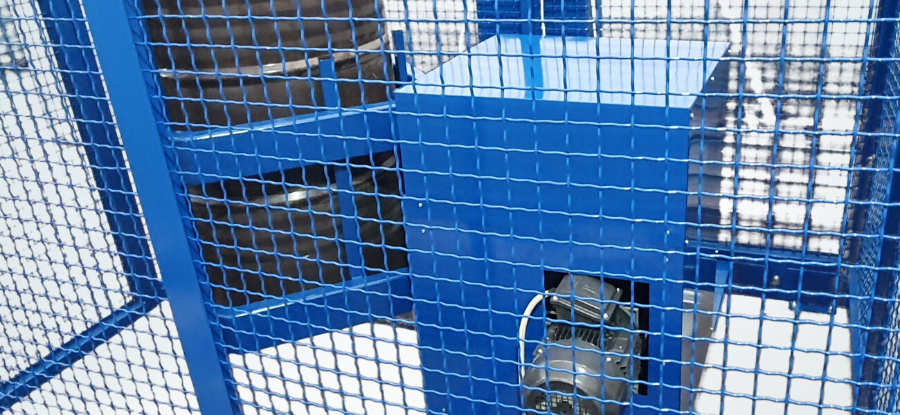
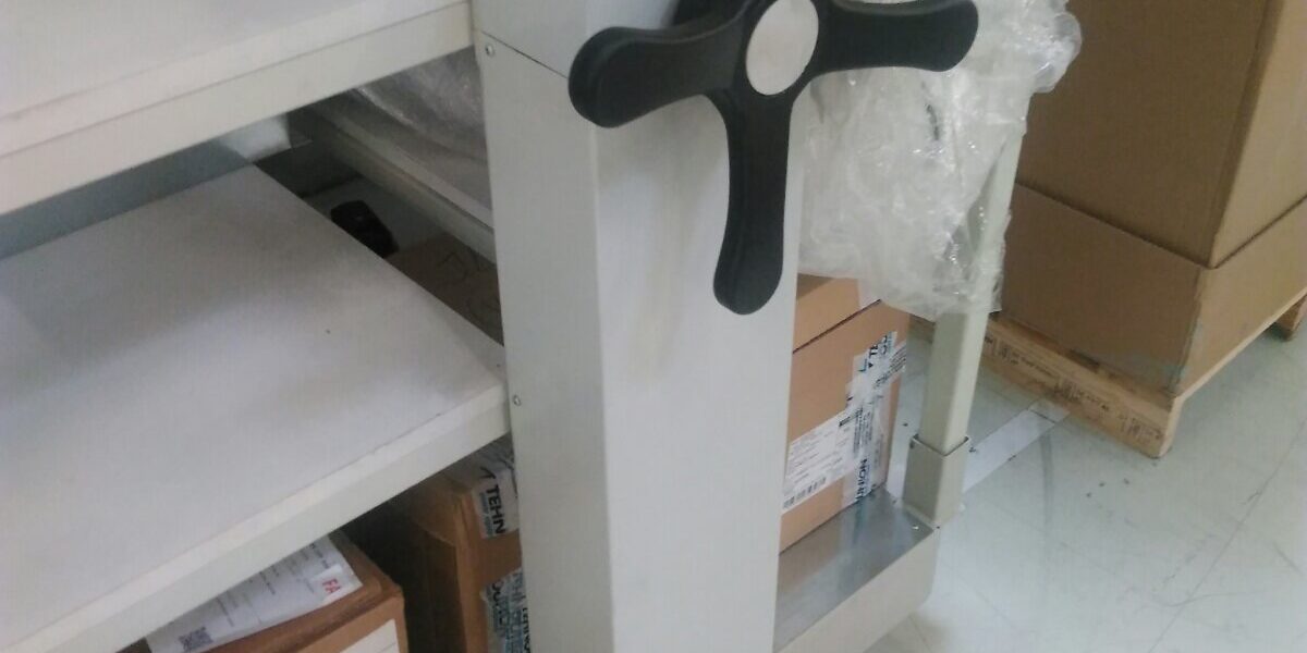
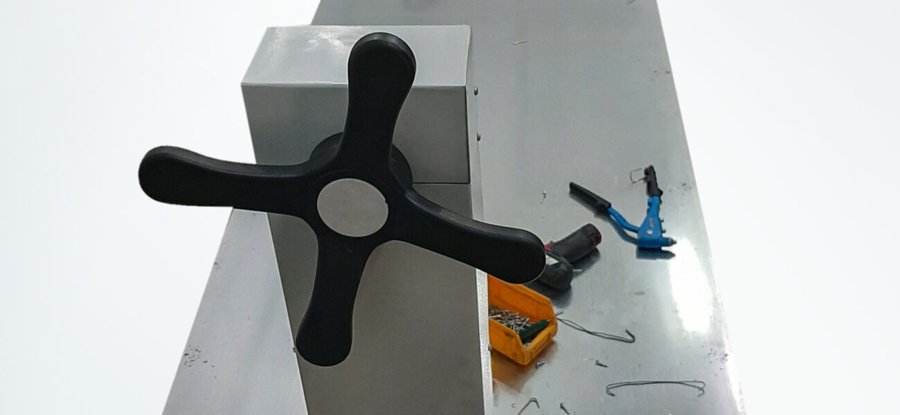
Mixer for mixing liquids in a 200 l barrel
Some liquid substances need to be mixed before use in the technological process.
One type of transport packaging has openings with lids of such a size that it is possible to place some kind of mixer through them and prepare the contents for use.
The second type does not have openings of the appropriate size for the passage of the mixer, so the mixing of the contents must be done by moving the whole vessel.
At the request of the customer, it was necessary to create a device that would mix the contents by turning over the closed container.
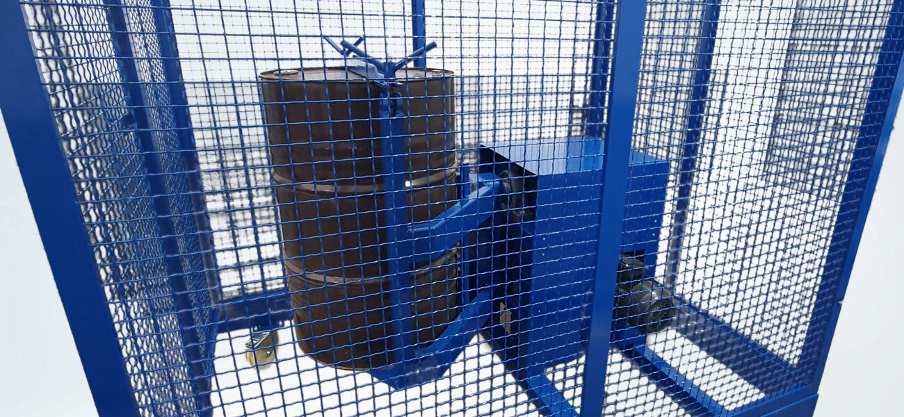
A well-known concept has been adopted, according to which the vessel (metal or plastic barrel) is placed on a slightly inclined receiving surface, fixed to it and, by activating the mechanism, mixing begins.
The proposed device allows selection of the speed (within the agreed range) and the duration of mixing.
The basis of the construction is a robust chassis, which is used to hold the barrels and accommodate the power unit.
The drive is an electric motor with a reducer, which is connected by a chain drive to the shaft that drives the receiving platform.
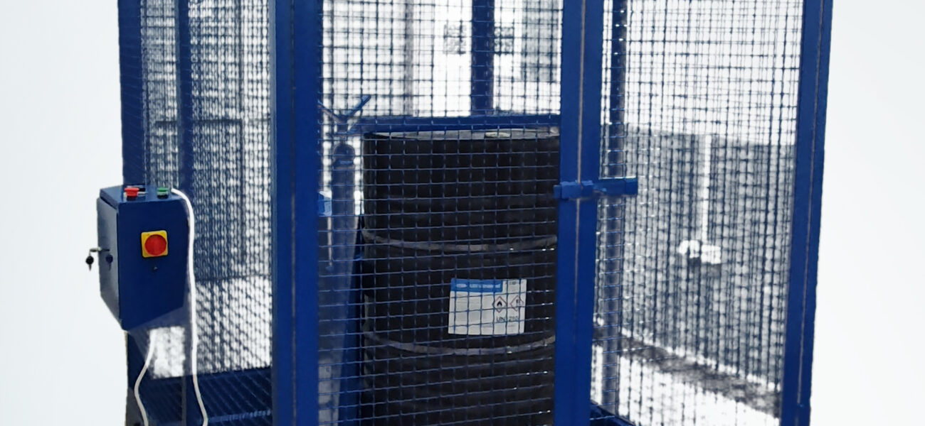
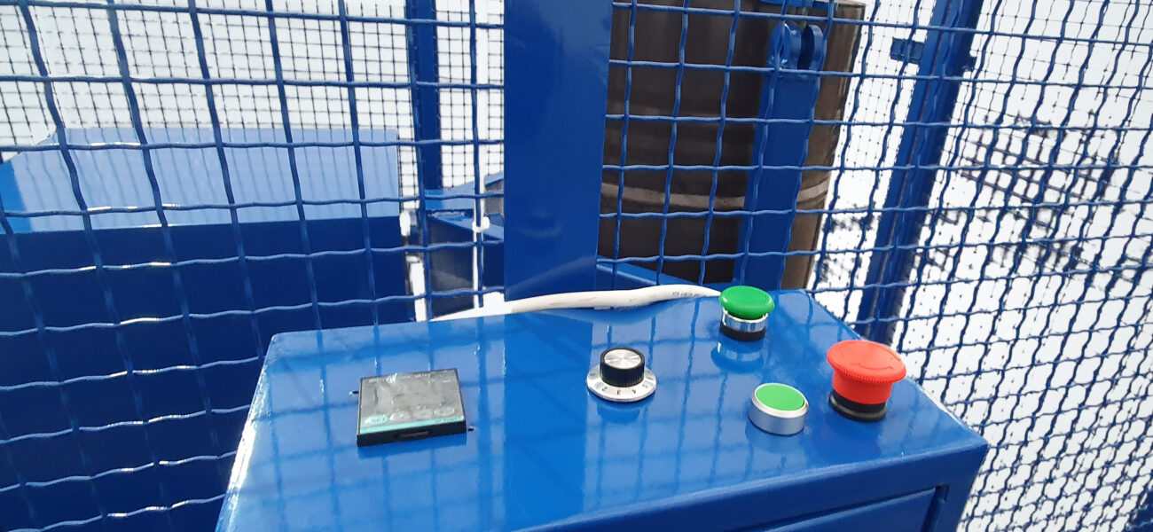
The device is managed from the control cabinet. On it there are start and stop buttons, a button for selecting the turning speed, a time timer button and the main switch.
The starting position of the receiving platform is horizontal – for easy adjustment of the barrels – and at the same time it is the final position of each cycle. We determine the length of the cycle by choosing the working time on the timer, but we can interrupt it if necessary with the stop button.
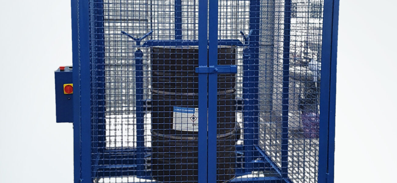
In order to protect the operator, it is planned to place a protective fence around the machine. The work cycle can only be activated after the door of the protective fence is closed.
Due to the presence of dynamic forces during rotation, the machine is fixed to the base.
Features of the device:
Barrel height: (800-920) mm
Barrel diameter: (450-600) mm
Rotation speed: (5-20) rpm
Load capacity: up to 350 kg
Engine power: 1.5 kW/380 V, 2800 rpm
Dimensions of the protective fence: (2250x1350x1600) mm
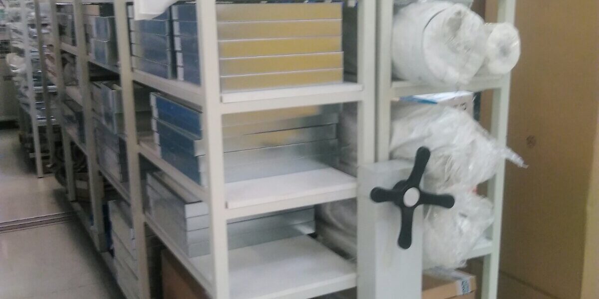
Mobile platform
This mechanism was designed to save space and improve item handling in:
- warehouses,
- storages
Whether in a production plant:
- library,
- gallery,
- documentation bureau,
- you name it.
You will save up to 40% space, and it will be incredibly easy to handle.
The main advantage of mobile platforms is that they make the most of the existing warehouse space. Platforms with racks or cabinets are arranged next to each other without spacing and in such an order they fill the room. When accessing one of them, the others are moved and allow approaching from one side or the other. After putting or taking items, the platforms return to the condensed order position.
The platform moves using wheels on floor rails.
The drive can be manual or electric.
It is also possible to apply computer management in storage system organization.
In this advanced variant, the user selects the desired item located somewhere in the warehouse; after processing information the platforms move in such a way as to allow access to the item on a particular platform – rack.
Platforms are made for different capacities, different dimensions, they can be complete with racks or cabinets, with manual or motorized drive – in a word, custom-made.
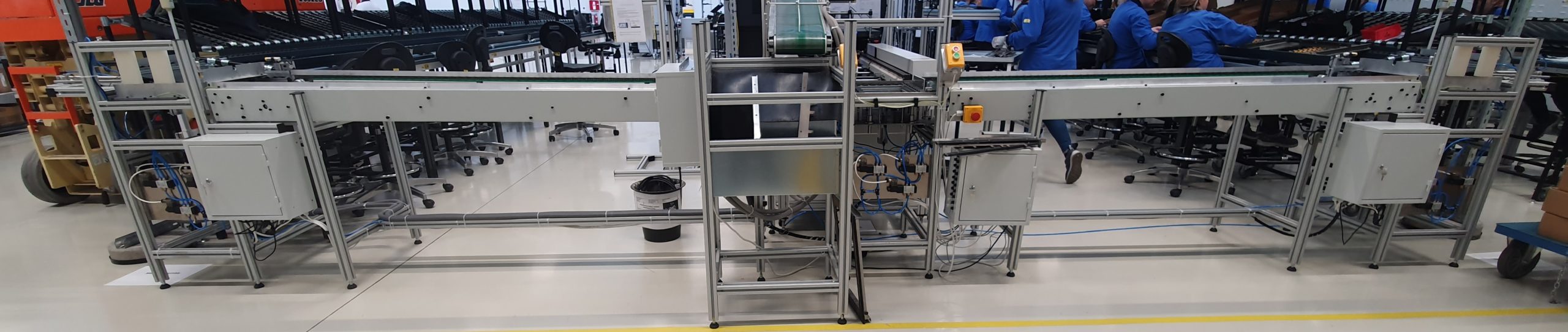
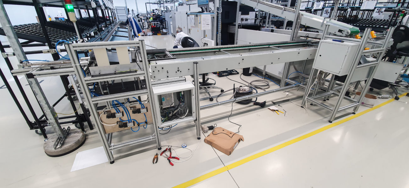
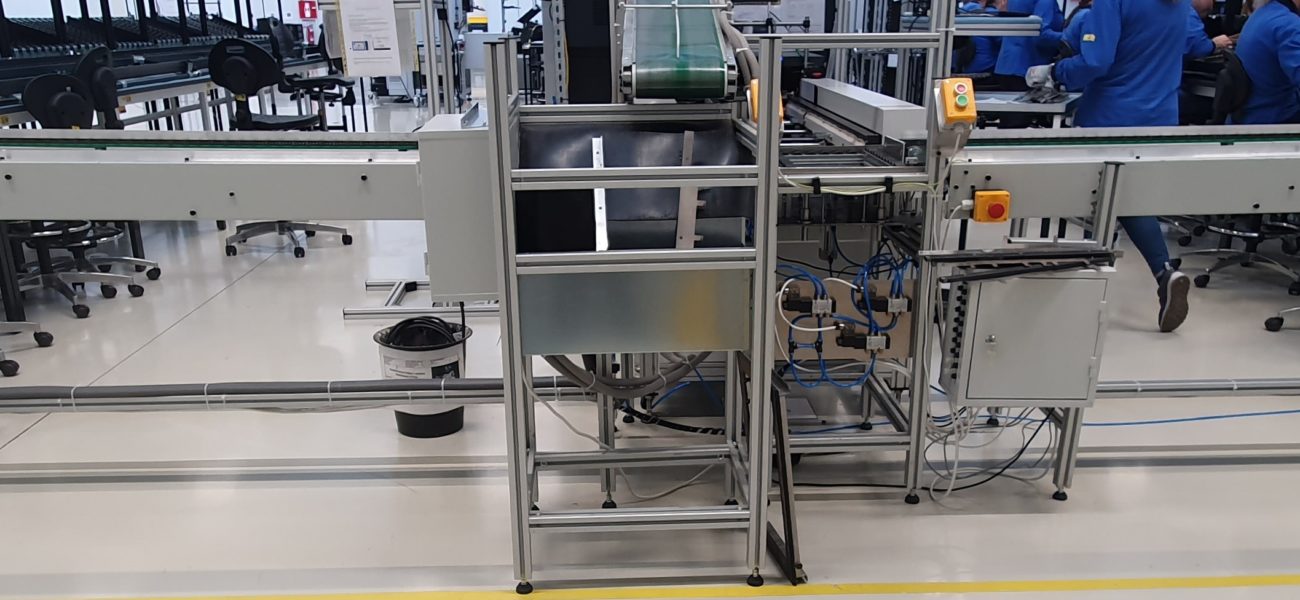
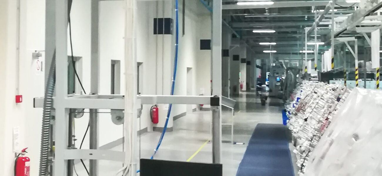
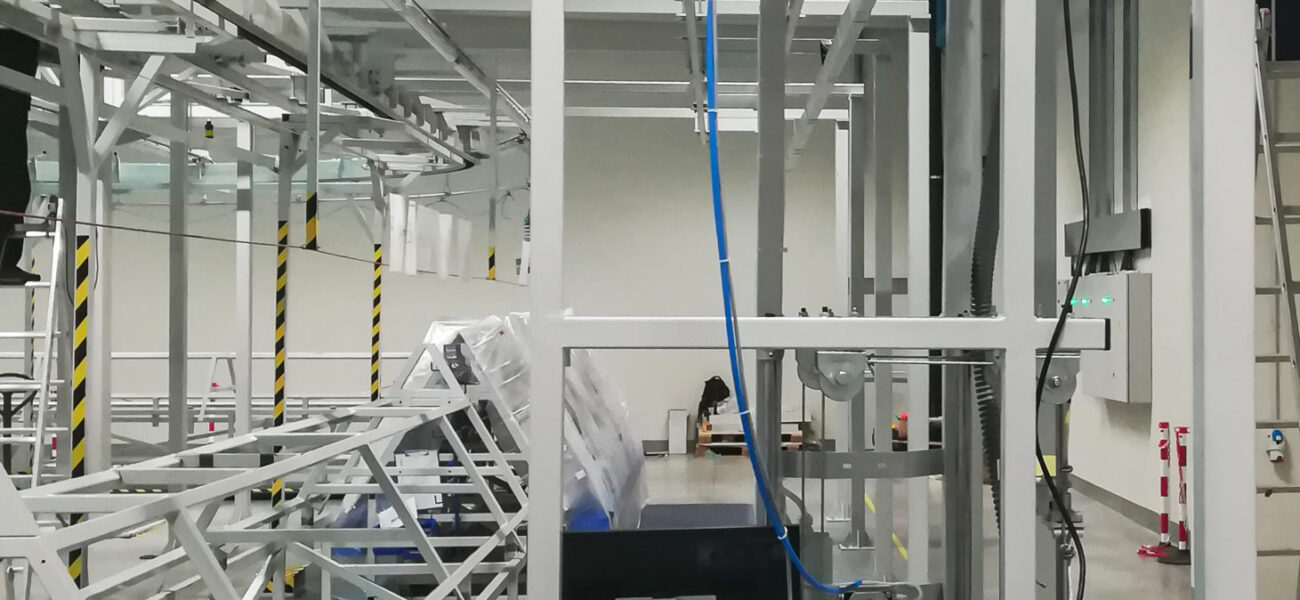
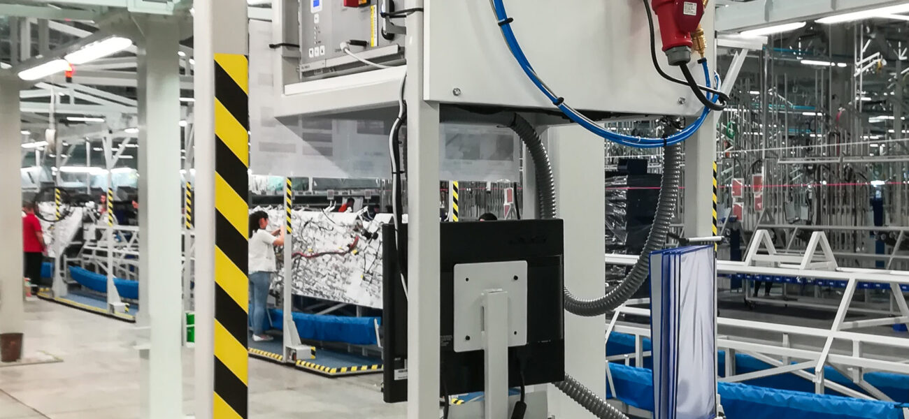
PCB board conveyor

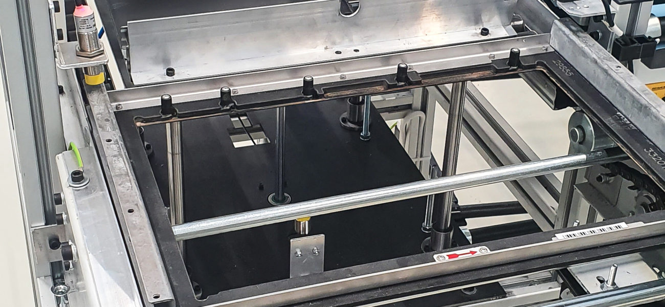
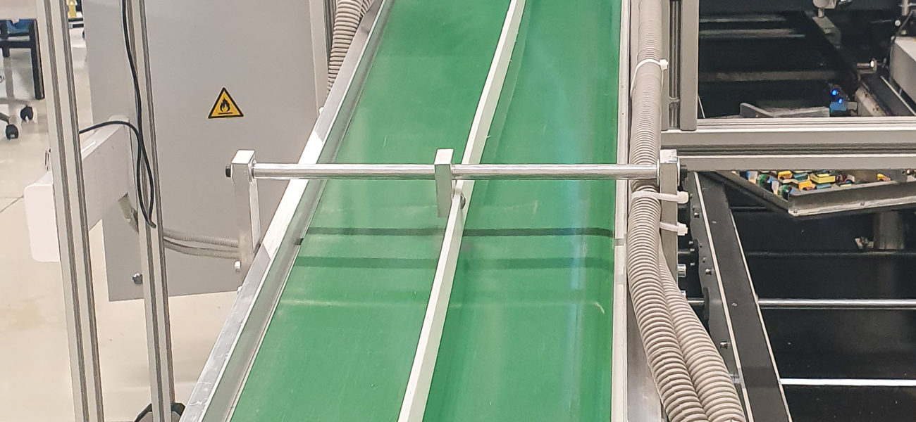
According to the customer’s request, it was necessary to make a conveyor that will transfer the frame with loaded printed circuit boards from the production line end point to the tin bath in the shortest possible time, in order to
- save time in transport,
- prevent the risk of components falling out of the board and
- reduce the number of operators involved in the transport itself.
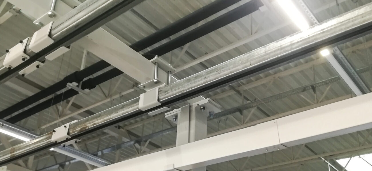
To this end, several functional units have been constructed and produced, interconnected into a PCB conveyor for the transport of loaded printed circuit boards.
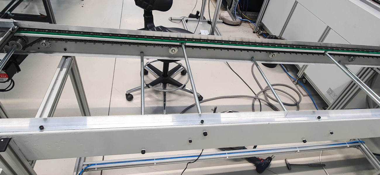
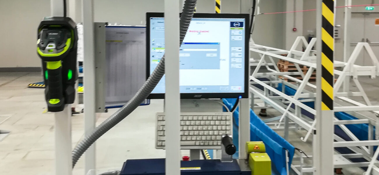
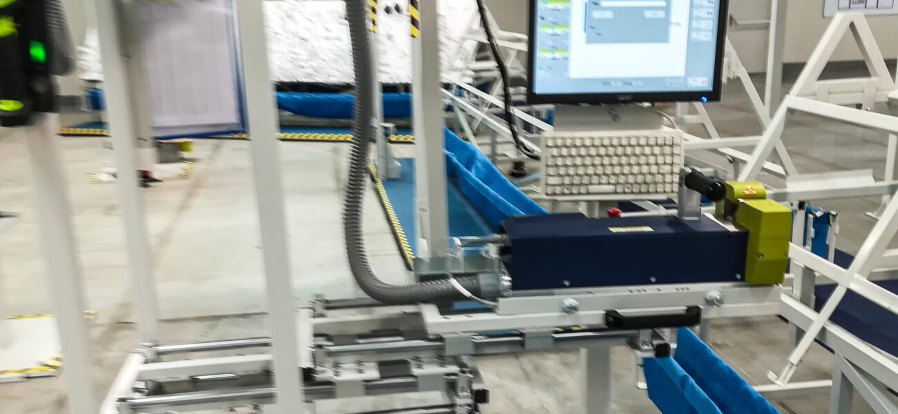
The conveyor line consists of a receiving station and chain conveyor tasked to transfer frames with loaded printed circuit boards.
The line serves two production lines at the same time.
Board production is a continuous process, and the devices making up the conveyor line work in continuous mode as follows:
- the frame with loaded printed circuit boards is placed on the receiving station,
- it descends to the conveyor height,
- the mechanism transfers it to the conveyor,
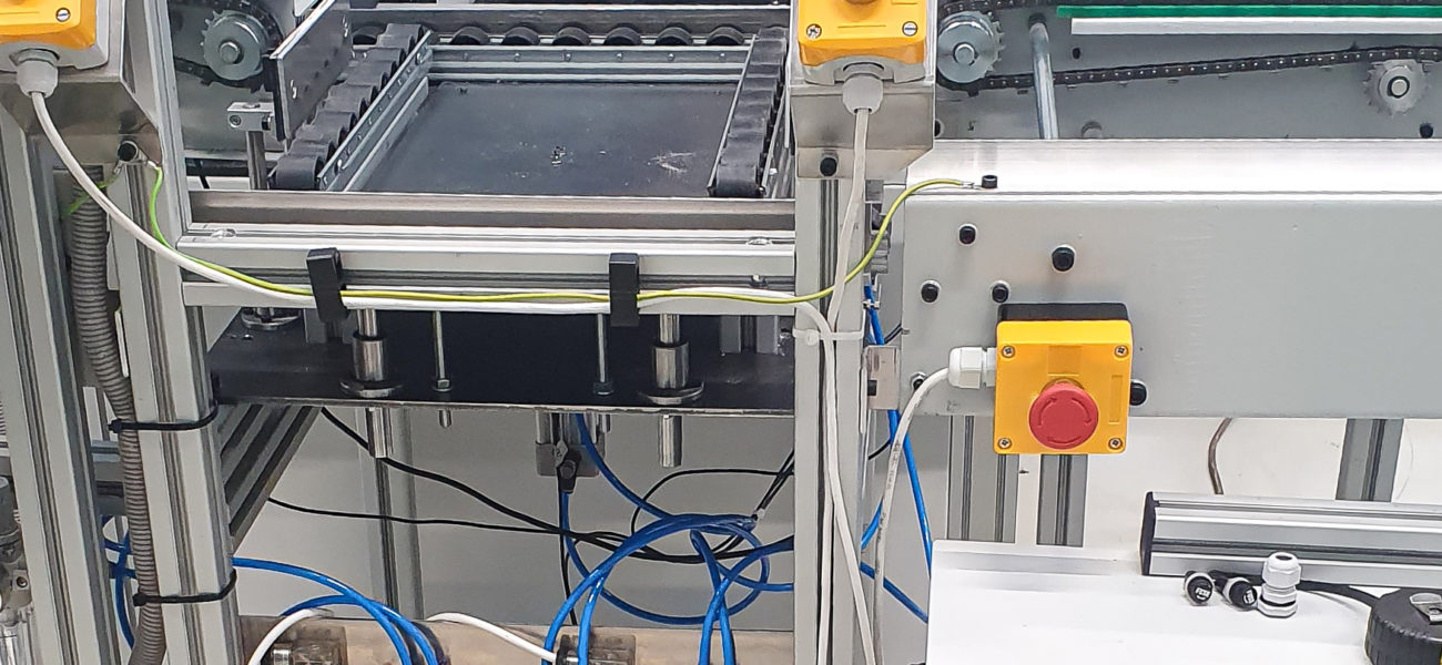
- the conveyor takes it to the next barrier mechanism, where it is stopped by a sensor switch
- the operator selects which of the two barriers to lower by pressing the button, and the conveyor continues
- at the entrance to the tin bath, the operator pushes the frame to the next transport mechanism
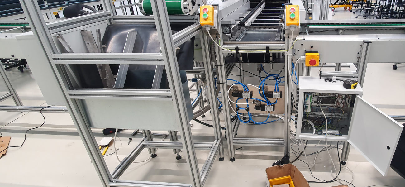
This job of aligning the order of operations is performed by the control system.
All operations during the transport of boards to the entrance to the tin bath take place according to a preset program.
The line is managed by the operator.
The boards come from two production lines at the same time, and the operator determines the order in which they go to the bath.
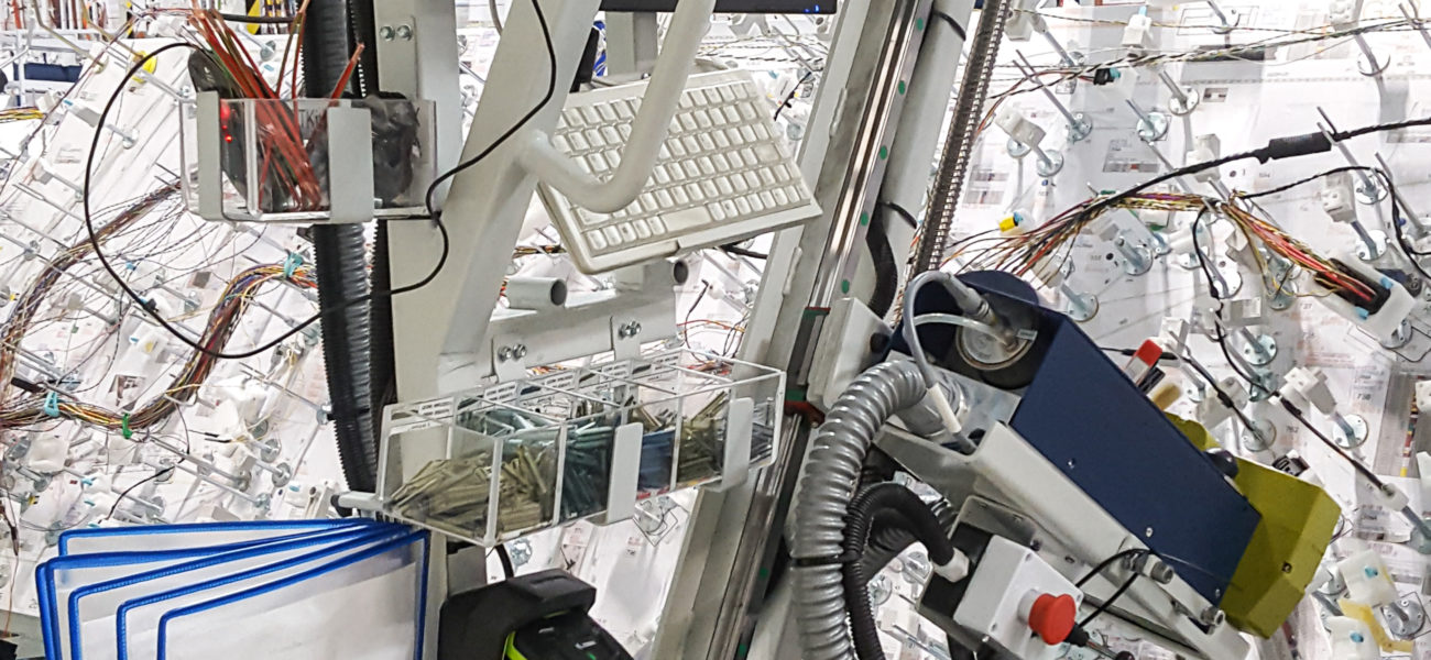
Ultrasonic welder positioning structure
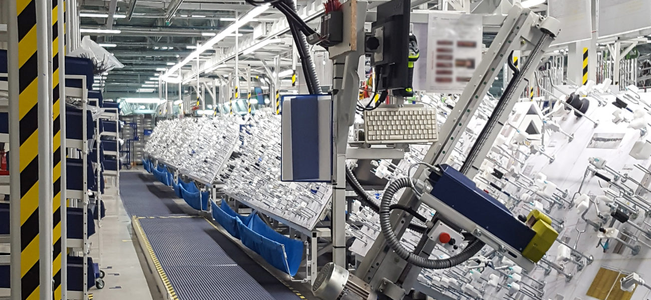
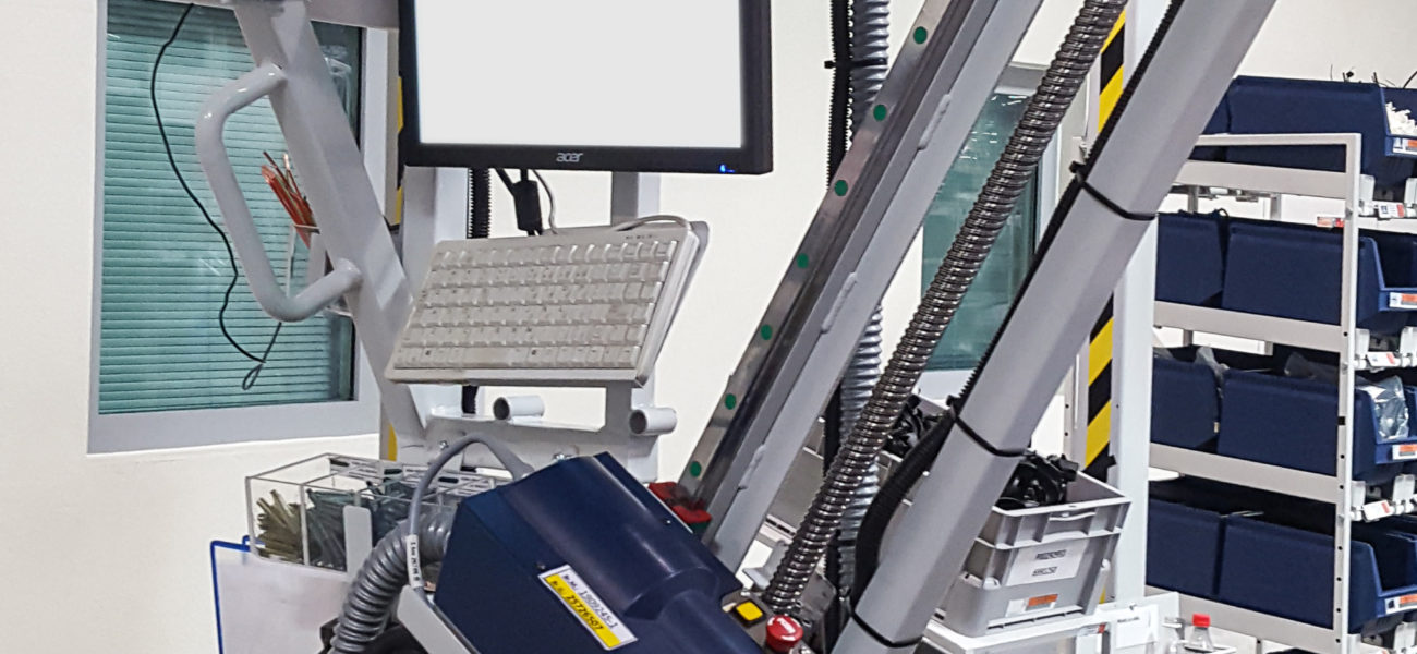

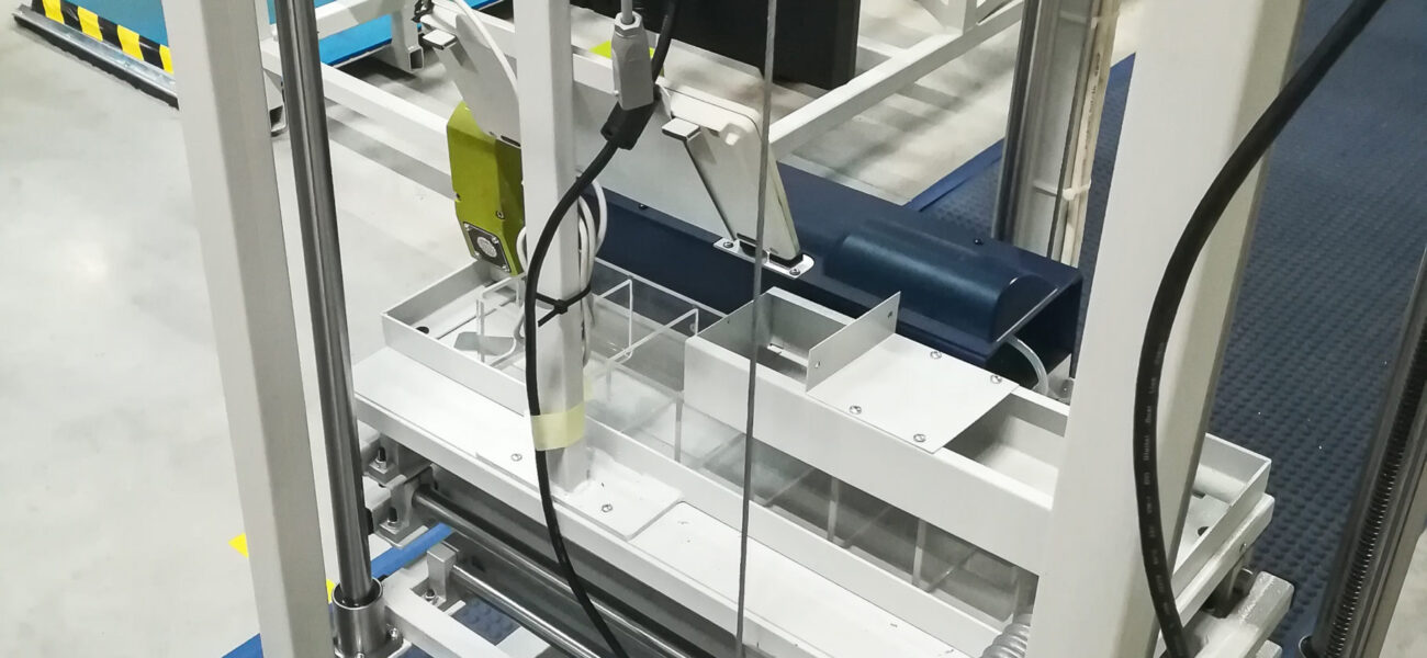
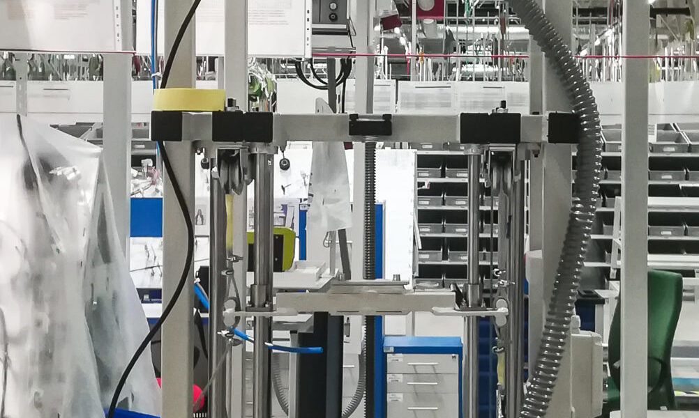
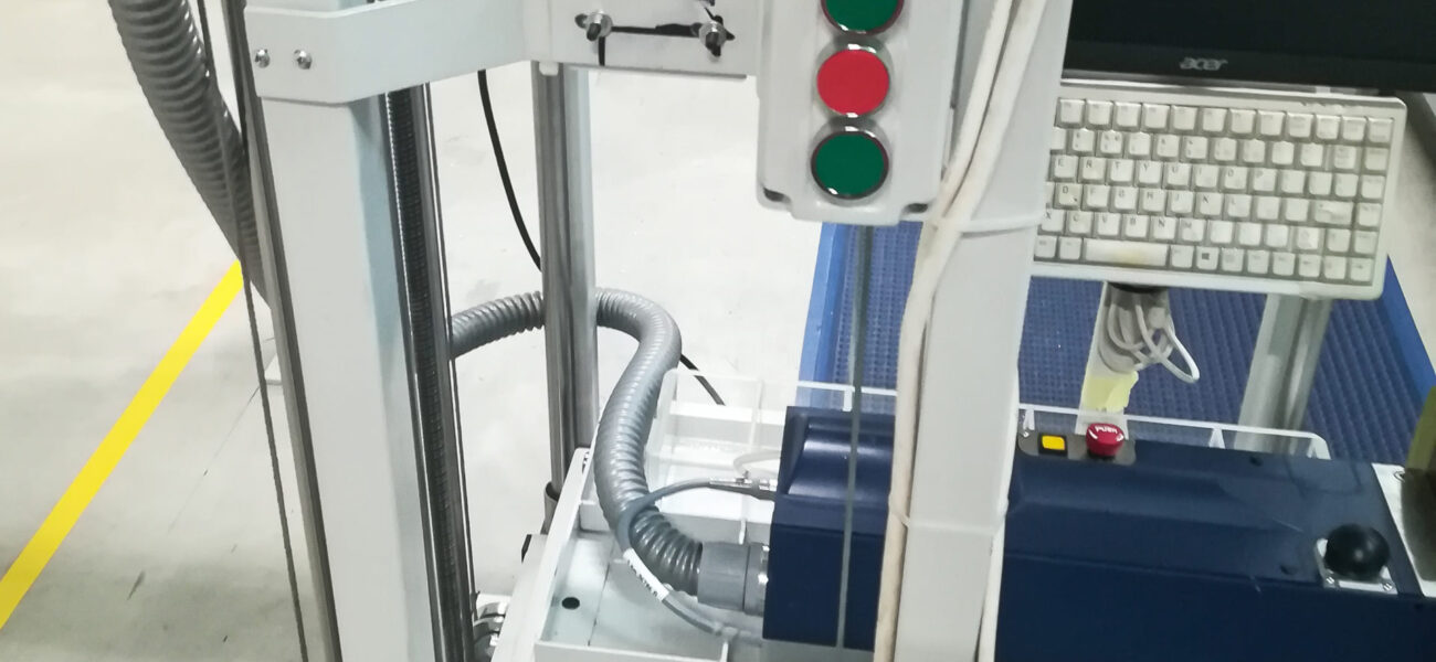
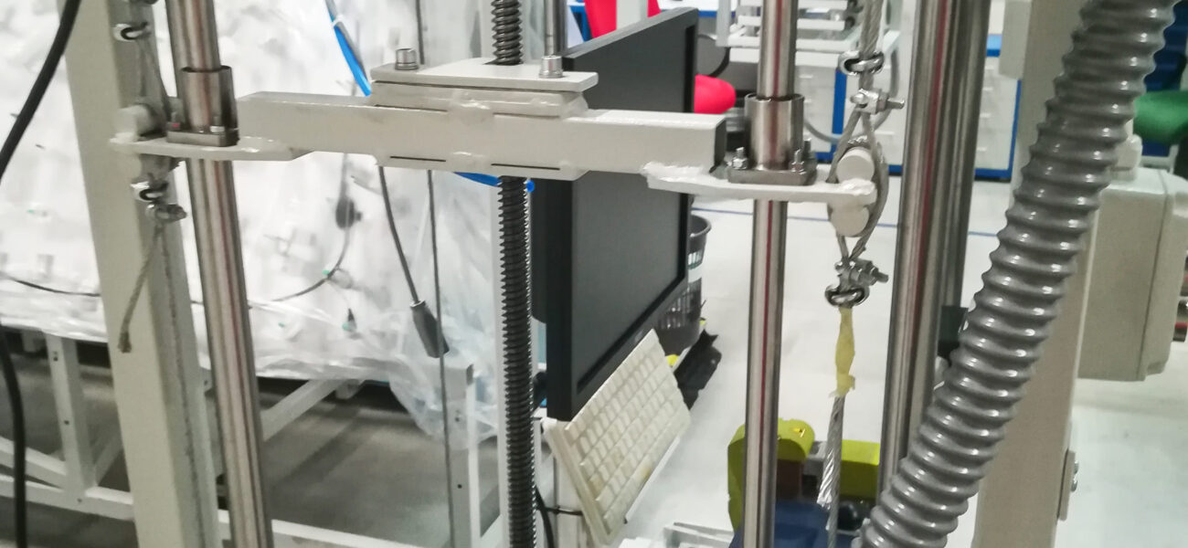
According to the customer’s request, it was necessary to make a steel structure that will be able to position the ultrasonic cable welder at a predefined range with the least possible physical effort of the operator.
The structure is made so that the operator can control the welder in three axes.
During the production of cable sets, which are made along a 10-12 m working line, there is a need for their ultrasonic welding. The line consists of a series of worktops, bent at a certain angle. The connection place is determined by the prescribed technological procedure and covers the entire worktop. This means that the welder needs to move in a horizontal and vertical – or oblique plane parallel to the worktop.
These movements are realized by means of different types of guides, mostly rolling, and the drives are manual and electric.
Manually the carrier moves in a horizontal plane in two axes. By moving along one axis, it goes along the entire technological line, and by moving along the other, in the direction perpendicular to the first, it approaches the worktop at the desired place. Vertical movement is performed by means of an electric motor drive.
In the oblique plane, the movement is defined from the worktop lower edge to the top. This movement is also performed by means of an electric motor drive.
The structure consists of:
- Steel columns,
- C profiles on which the sliders carrying the mobile platform move,
- Steel boxes that form the mobile platform to which the welder and complete control electronics are directly connected.
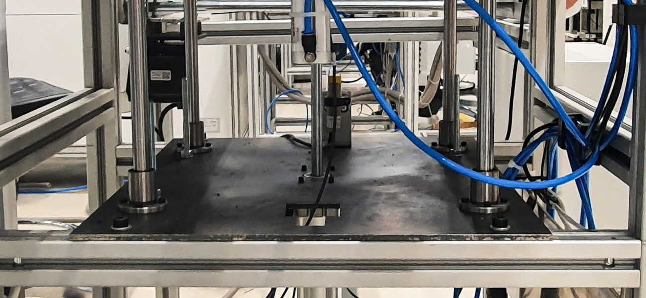
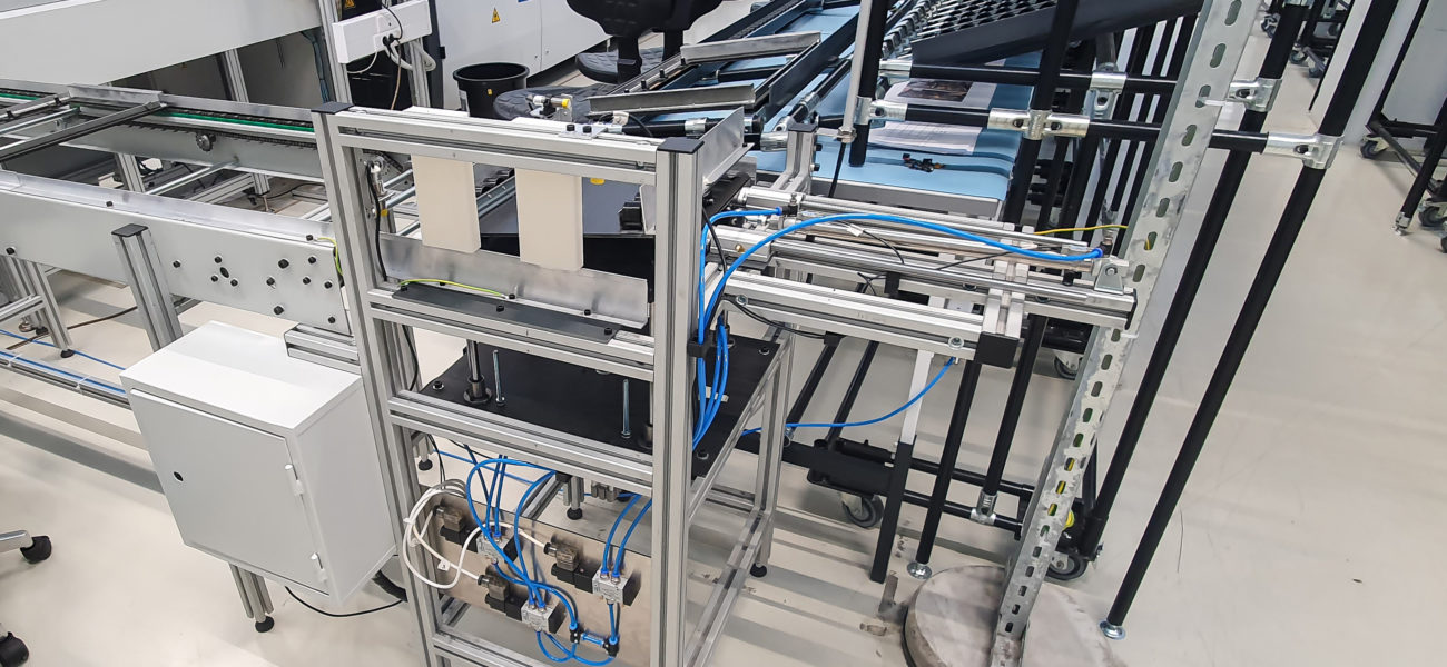
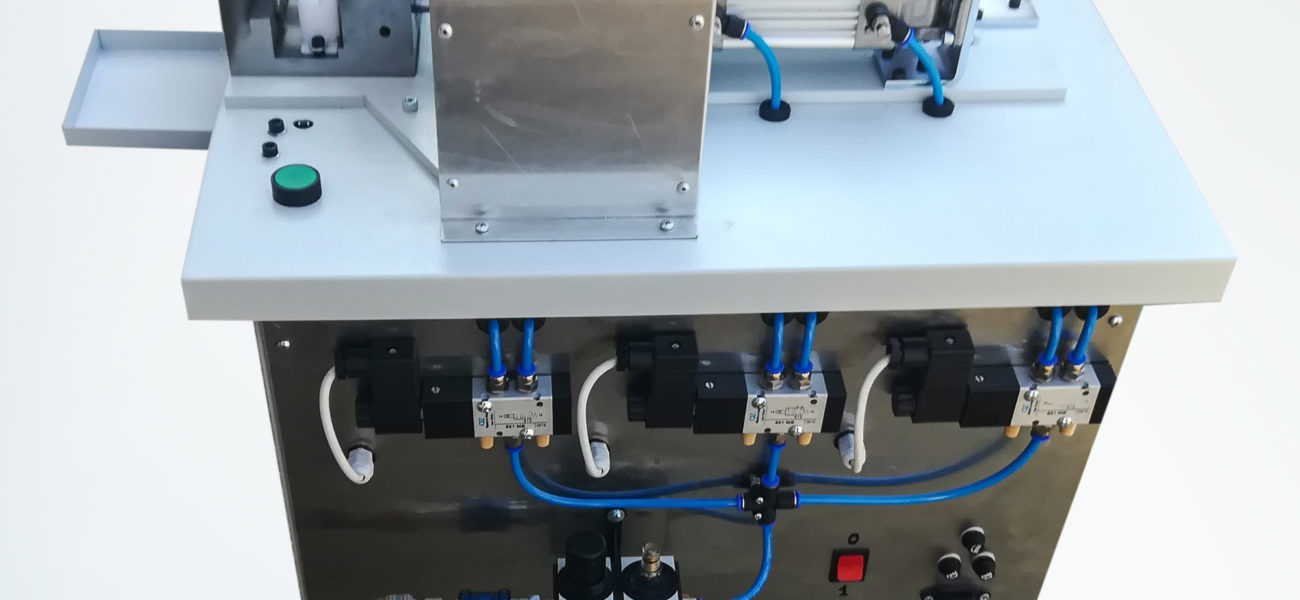
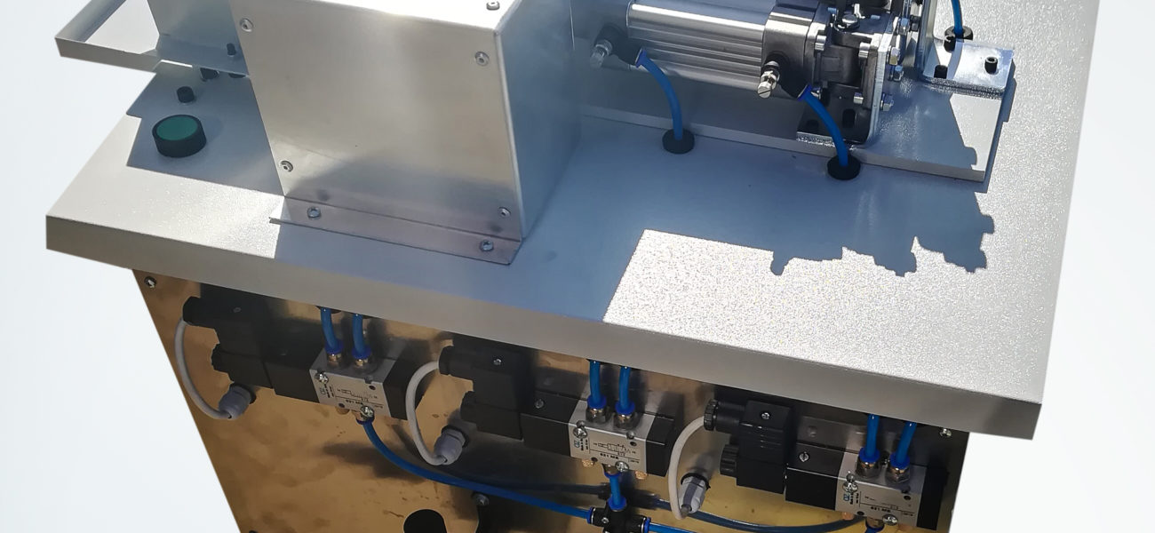
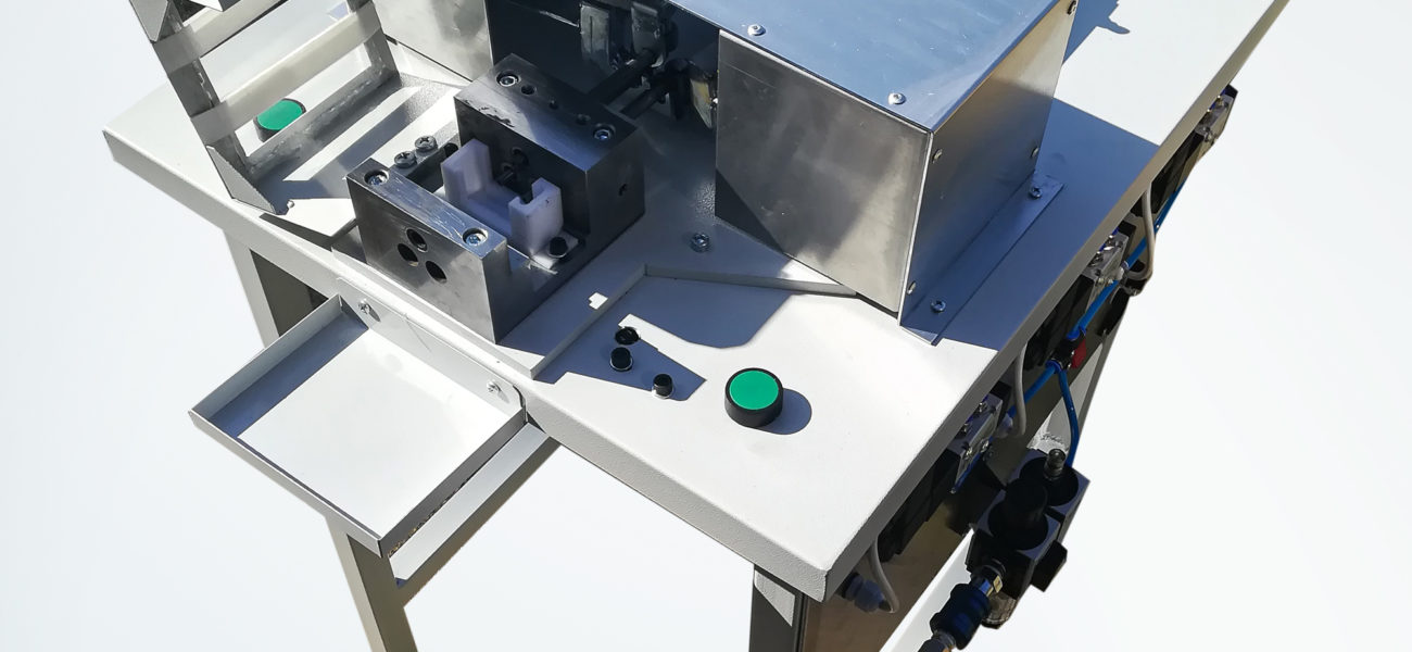
Rubber castings punching device

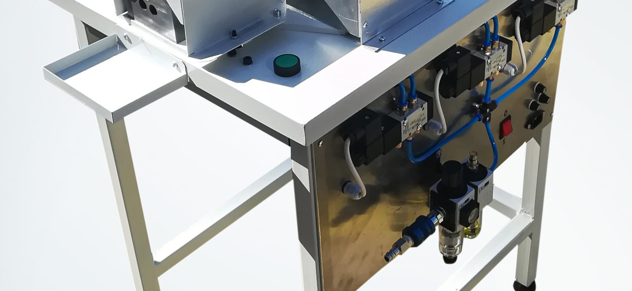
When making a rubber element by injection molding, in two or three places where openings for the passage of cables and the like are planned, two or three formed channels exit the tool with closed ends.
The need for production is to remove – break through the ends, the first or the second, or the third or all three OF THEM.
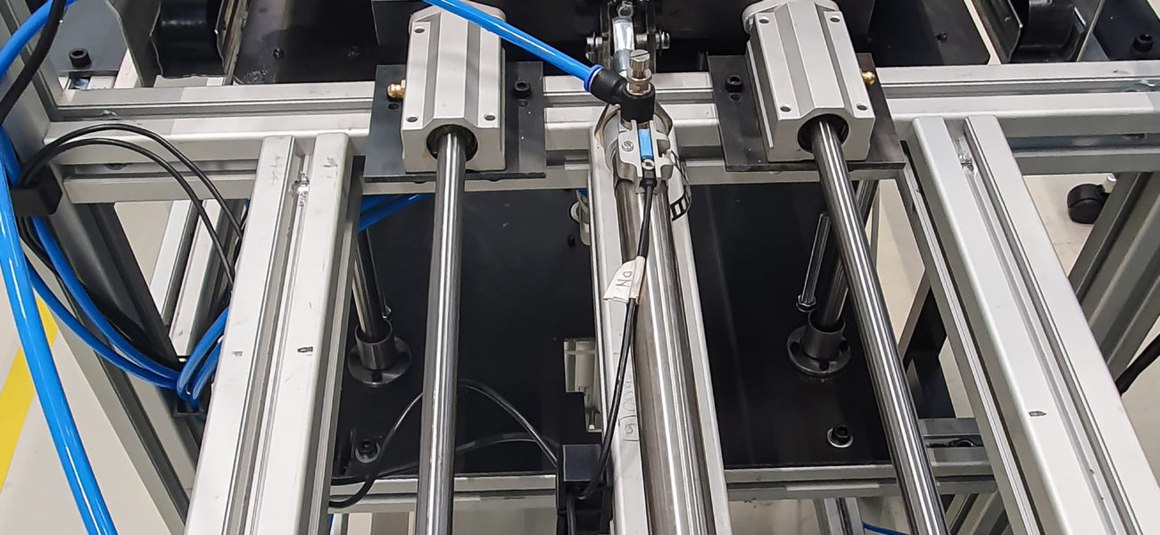
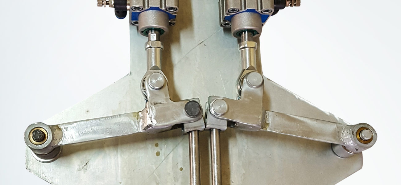
Punchers and cutting sleeves are made of high quality tool steel, hardened and ground.
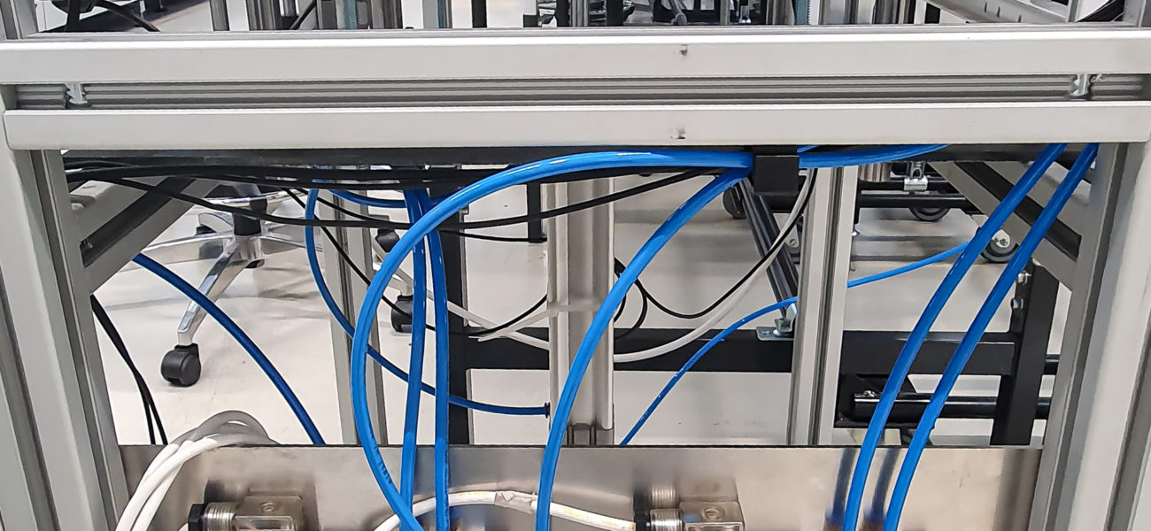
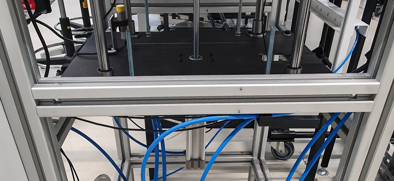
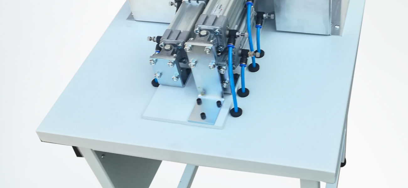
Punchers move back and forth by the action of pneumatic cylinders on specially designed levers.
Pneumatic cylinders are controlled by solenoid directional control valves with elements making up the pneumatic installation.
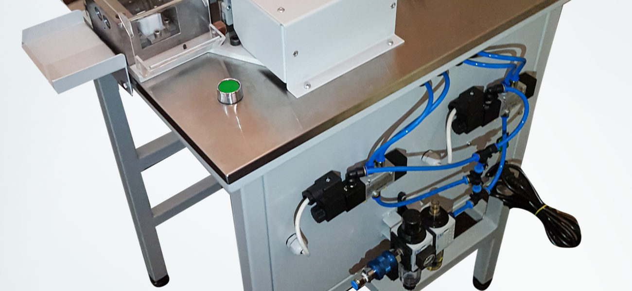
Solenoid directional control valve commands are given via the button.
To protect users against possible injuries, there is a cover in the work area that closes the space around the punching part.